
[su_accordion]
[su_spoiler title=”Default maXimator demo project ” icon=”folder-1″]
[su_youtube_advanced url=”https://www.youtube.com/watch?v=tEE15cCcIXQ” width=”540″ height=”320″ responsive=”no”]
Complex example (default for maXimator, programmed in FPGA’s Flash memory), using most maXimator and maXimator Expander (Arduino Uno compatible shield) peripherals (i.a. VGA interface, 7-seg LED displays, pushbuttons, on-board LEDs and one-wire RGB-LEDs – WS2812B).
Complete project for free Altera Quartus Prime Lite synthesis tool.
Top-level entity is schematic. In project were used free LPM parametrized Altera components and VHDL modules too.
Author: KAMAMI.pl.
[su_custom_gallery source=”media: 184,185,186,187,188,189,190,191,192″ link=”lightbox” target=”blank” width=”70″ height=”100″][/su_custom_gallery]
[su_button url=”https://maximator-fpga.org/wp-content/uploads/2016/02/MAXimator_demo_v1_0.zip” target=”blank” style=”soft” background=”#ca9a1e” icon=”icon: cloud-download”] Project download[/su_button]
[/su_spoiler]
[su_spoiler title=”Pushbutton debouncer (VHDL IP Core + complete Quartus Prime project)” icon=”folder-1″]
[su_youtube_advanced url=”https://www.youtube.com/watch?v=iwcpgyzbu1U” width=”540″ height=”320″ responsive=”no”]
Hardware implemented 1-channel debouncer to eliminate pushbutton contacts vibration effects. Debouncer module demands 50MHz clock signal that is produced by internal PLL (as shown in the example).
Complete project for free Altera Quartus Prime Lite synthesis tool.
Top-level entity is schematic. In project were used free LPM parametrized Altera components and VHDL modules too.
Author: KAMAMI.pl.
[su_custom_gallery source=”media: 209,217,216,215,214,213,212,211,210″ link=”lightbox” target=”blank” width=”70″ height=”100″][/su_custom_gallery]
[su_button url=”https://maximator-fpga.org/wp-content/uploads/2016/02/pushbutton-debouncer_V1_0.zip” target=”blank” style=”soft” background=”#ca9a1e” icon=”icon: cloud-download”] Project download[/su_button]
[/su_spoiler]
[su_spoiler title=”VGA 800×600 px tester (VHDL IP Core + complete Quartus Prime project)” icon=”folder-1″]
[su_youtube_advanced url=”https://www.youtube.com/watch?v=uWzyqRzMRSI” width=”540″ height=”320″ responsive=”no”]
Simple VGA video generator (RGB test picture). Module demands 40MHz clock signal that is produced by internal PLL (as shown in the example).
Complete project for free Altera Quartus Prime Lite synthesis tool.
Top-level entity is schematic. In project were used free LPM parametrized Altera components and VHDL modules too.
Author: KAMAMI.pl.
[su_custom_gallery source=”media: 261,269,268,267,266,265,264,263,262″ link=”lightbox” target=”blank” width=”60″ height=”100″][/su_custom_gallery]
[su_button url=”https://maximator-fpga.org/wp-content/uploads/2016/02/MAXimator-VGA-test_v1_0.zip” target=”blank” style=”soft” background=”#ca9a1e” icon=”icon: cloud-download”] Project download[/su_button]
[/su_spoiler]
[su_spoiler title=”7-segments mux-LED controllers – 3 versions (IP Cores + complete Quartus Prime project)” icon=”folder-1″]
[su_youtube_advanced url=”https://www.youtube.com/watch?v=eswA51v4psk” width=”540″ height=”320″ responsive=”no”]
Three versions of 4-digits, 7-segments, multiplexed LED display controllers:
- based on classical 7447 (TTL family) 7-segments decoder,
- improved version (VHDL) with modern look of 6 and 9 characters + signalling out-of range input value (>9),
- BIN>HEX decoder described in VHDL.
All examples were tested with 74192 or 74193 up-down counters (TTL family) in complete projects available to download.
Projects are compatible with free Altera Quartus Prime Lite synthesis tool.
Top-level entity is schematic. In project were used free LPM parametrized Altera component (counter) and VHDL modules too.
Author: KAMAMI.pl.
[su_custom_gallery source=”media: 287,288,289,290,291,292,293,294,295″ link=”lightbox” target=”blank” width=”60″ height=”100″][/su_custom_gallery]
[su_button url=”https://maximator-fpga.org/wp-content/uploads/2016/02/MAXimator-7seg-4dig-mux-7447_v1_0.zip” target=”blank” style=”soft” background=”#ca9a1e” icon=”icon: cloud-download”] Project based on 7447[/su_button]
[su_button url=”https://maximator-fpga.org/wp-content/uploads/2016/02/MAXimator-7seg-4dig-mux-modified_6_and_9_V1_0.zip” target=”blank” style=”soft” background=”#ca9a1e” icon=”icon: cloud-download”] Project based on VHDL improved version of 7447[/su_button]
[su_button url=”https://maximator-fpga.org/wp-content/uploads/2016/02/MAXimator-7seg-4digs-mux-HEX_V1_0.zip” target=”blank” style=”soft” background=”#ca9a1e” icon=”icon: cloud-download”] Project based on BIN>HEX VHDL decoder[/su_button]
[/su_spoiler]
[su_spoiler title=”Pomodoro Timer described in VHDL (complete Quartus Prime project)” icon=”folder-1″]
[su_youtube_advanced url=”https://www.youtube.com/watch?v=Blv5Nbi8gWc” width=”540″ height=”320″ responsive=”no”]
Pomodoro Timer is a hardware tool for time management idea, described in Wikipedia.
All modules used in project were described in VHDL and are available to download. User manual is available in the above video.
Project is compatible with free Altera Quartus Prime Lite synthesis tool.
Top-level entity is VDHL file.
Author: Paweł Żuk.
[su_custom_gallery source=”media: 326,327,328,329,330,331,332,333,334″ link=”lightbox” target=”blank” width=”60″ height=”100″][/su_custom_gallery]
[su_button url=”https://maximator-fpga.org/wp-content/uploads/2016/02/MAXimator-pomodoro-timer.zip” target=”blank” style=”soft” background=”#ca9a1e” icon=”icon: cloud-download”] Project download[/su_button]
[/su_spoiler]
[su_spoiler title=”Simple voltage meter based on internal ADC (IP cores + VHDL – complete Quartus Prime project)” icon=”folder-1″]
[su_youtube_advanced url=”https://www.youtube.com/watch?v=Pcr3ilBs_dc” width=”540″ height=”320″ responsive=”no”]
Example of simple voltage meter FPGA implementation, based on internal (built in MAX10) 12-b ADC. Results of ADC conversions are displayed on 4-digits 7-segments LED diplays in BCD representation (without any scaling – 12-bit binary value is converted to BCD value in range 0-4095). ADC measures voltage on dedicated ANIN FPGA pin with slider of analog potentiometer connected.
Modules used in project were described in VHDL and are available to download. User manual is available in the above video.
Project is compatible with free Altera Quartus Prime Lite synthesis tool.
Top-level entity is VDHL file.
Author: Mariusz Księżak.
[su_custom_gallery source=”media: 348,349,350,351,352,353,354,355,356″ link=”lightbox” target=”blank” width=”60″ height=”100″][/su_custom_gallery]
[su_button url=”https://maximator-fpga.org/wp-content/uploads/2016/02/MAXimator-ADC-test.zip” target=”blank” style=”soft” background=”#ca9a1e” icon=”icon: cloud-download”] Project download[/su_button]
[/su_spoiler]
[su_spoiler title=”Bidirectional UART core + communication with external device (IP core + VHDL – complete Quartus Prime project)” icon=”folder-1″]
[su_youtube_advanced url=”https://www.youtube.com/watch?v=mLytDDPt7Xk” width=”540″ height=”320″ responsive=”no”]
Bidirectional UART core implementation – example of PCFPGA data exchange. HEX codes of received characters are displayed on 7-segments LED displays, UART core resend to PC all received characters. maXimator board must be equipped with UART/USB converter (like ZL5USB by KAMAMI or similar, based on FTDI or Microchip one-chip protocol converters). Default transmission parameteres: 115 kb/s, 8n1, no flow control.
Modules used in project were described in VHDL and are available to download. User manual is available in the above video.
Project is compatible with free Altera Quartus Prime Lite synthesis tool.
Top-level entity is VDHL file.
Author: Paweł Żuk.
[su_custom_gallery source=”media: 370,371,372,373,374,375,376,377,378″ link=”lightbox” target=”blank” width=”60″ height=”100″][/su_custom_gallery]
[su_button url=”https://maximator-fpga.org/wp-content/uploads/2016/02/MAXimator-UART-echo.zip” target=”blank” style=”soft” background=”#ca9a1e” icon=”icon: cloud-download”] Project download[/su_button]
[/su_spoiler]
[su_spoiler title=”Snake game with VGA output implemented in FPGA” icon=”folder-1″]
[su_youtube_advanced url=”https://www.youtube.com/watch?v=iqsONraCDKo” width=”540″ height=”320″ responsive=”no”]
Simple version of famous Snake game with VGA video output. Two on-board pushbuttons (L, R) are dedicated to change direction of movement of the snake, one is dedicated to restart game. Collected points are displayed on 4-digs/7-segments on-board displays.
Modules used in project were described in VHDL and are available to download. User manual is available in the above video.
Project is compatible with free Altera Quartus Prime Lite synthesis tool.
Top-level entity is VDHL file.
Author: Paweł Żuk.
[su_custom_gallery source=”media: 392,393,394,395,396,397,398,399,400″ link=”lightbox” target=”blank” width=”60″ height=”100″][/su_custom_gallery]
[su_button url=”https://maximator-fpga.org/wp-content/uploads/2016/07/MAXimator-Snake-game.zip” target=”blank” style=”soft” background=”#ca9a1e” icon=”icon: cloud-download”] Project download[/su_button]
[/su_spoiler]
[su_spoiler title=”WS2812 RGB-LED remote controller based on vCOM-UART communication” icon=”folder-1″]
[su_youtube_advanced url=”https://www.youtube.com/watch?v=sqyXgxemAzE” width=”540″ height=”320″ responsive=”no”]
Remote controlled LED-RGB (on-board WS2812B) driver. User can change colour and LED light intensity by 6 hexadecimal characters sent from terminal emulator software running on PC. maXimator board must be equipped with UART/USB converter (like ZL5USB by KAMAMI or similar, based on FTDI or Microchip one-chip protocol converters). Default transmission parameteres: 115 kb/s, 8n1, no flow control.
Modules used in project were described in VHDL and are available to download. User manual is available in the above video.
Project is compatible with free Altera Quartus Prime Lite synthesis tool.
Top-level entity is VDHL file.
Author: Paweł Żuk.
[su_custom_gallery source=”media: 412,413,414,415,416,417,418,419,420″ link=”lightbox” target=”blank” width=”60″ height=”100″][/su_custom_gallery]
[su_button url=”https://maximator-fpga.org/wp-content/uploads/2016/10/MAXimator_uart_led_config.zip” target=”blank” style=”soft” background=”#ca9a1e” icon=”icon: cloud-download”] Project download[/su_button]
[/su_spoiler]
[su_spoiler title=”Simple DSO (oscilloscope) based on maXimator’s FPGA” icon=”folder-1″]
[su_youtube_advanced url=”https://www.youtube.com/watch?v=sqyXgxemAzE” width=”540″ height=”320″ responsive=”no”]
Simple DSO (Digital Storage Oscilloscope) based on ADC built-in MAX10 FPGA. In presented example samples frequency is 500 Hz. In each acquistion FPGA collects and displays 1024 samples. Signal shape in displayed on VGA monitor (1024×768/60Hz mode).
Modules used in project were described in VHDL and QSys and are available to download. User manual is available in the above video.
Project is compatible with free Altera Quartus Prime Lite synthesis tool.
Top-level entity is VDHL file.
Author: Piotr Rzeszut, AGH.
[su_custom_gallery source=”media: 422,423,424,425,426,427,428,429,430″ link=”lightbox” target=”blank” width=”60″ height=”100″][/su_custom_gallery]
[su_button url=”https://maximator-fpga.org/wp-content/uploads/2016/10/MAXimator-DSO.zip” target=”blank” style=”soft” background=”#ca9a1e” icon=”icon: cloud-download”] Project download[/su_button]
[/su_spoiler]
[su_spoiler title=”Digital thermometer with STLM20 analog sensor and 7-seg LED display” icon=”folder-1″]
[su_youtube_advanced url=”https://www.youtube.com/watch?v=i5E-wDHVrNE” width=”540″ height=”320″ responsive=”no”]
Digital thermometer with analog STLM20 temperature sensor is based on ADC built-in MAX10 FPGA. In presented example temperature is displayed on 7-seg LED display. Both: displays and temperature sensor are mounted on maXimator shield.
Modules used in project were described in VHDL, top of project is schematic. User manual is available in the above video.
Project is compatible with free Intel Quartus Lite synthesis tool.
Author: Przemysław Sala, AGH.
[su_custom_gallery source=”media: 468,469,470,471,472,473″ link=”lightbox” target=”blank” width=”60″ height=”100″][/su_custom_gallery]
[su_button url=”https://maximator-fpga.org/wp-content/uploads/2016/02/maXimator-thermometer-7seg-display.zip” target=”blank” style=”soft” background=”#ca9a1e” icon=”icon: cloud-download”] Project download[/su_button]
[/su_spoiler]
[su_spoiler title=”PONG game with analog joystick and HDMI output” icon=”folder-1″]
[su_youtube_advanced url=”https://www.youtube.com/watch?v=q2vS937Tl9g” width=”540″ height=”320″ responsive=”no”]
Single player PONG game implementation is based on maXimator main board and shield, which is included in promotional edition of maXimator eval board. Video signal is generated in HDMI module and described in VHDL, in module with game engine.
In project are used: VHDL module, old-style (from MAX+Plus II) TTL counter 74169 and PLL module generated by QSys. Top of presented project is schematic. User manual is available in the above video.
Project is compatible with free Intel Quartus Lite synthesis tool.
Author: Piotr Chodorowski.
[su_custom_gallery source=”media: 482,483,484,485,486,487,488,489,490″ link=”lightbox” target=”blank” width=”60″ height=”100″][/su_custom_gallery]
[su_button url=”https://maximator-fpga.org/wp-content/uploads/2016/02/MAXimator-PONG-HDMI.zip” target=”blank” style=”soft” background=”#ca9a1e” icon=”icon: cloud-download”] Project download[/su_button]
[/su_spoiler]
[su_spoiler title=”Simple HDMI video signal generator/tester” icon=”folder-1″]
[su_youtube_advanced url=”https://www.youtube.com/watch?v=agKPjtTc7_g” width=”540″ height=”320″ responsive=”no”]
HDMI video generator (vertical stripes in 8 colours, 640×480 pixels @60Hz) described in Verilog HDL. User manual is available in the above video.
Project is compatible with free Intel Quartus Lite 16.1 synthesis tool.
Author: Michał Kozioł.
[su_custom_gallery source=”media: 392,393,394,395,396,397,398,399,400″ link=”lightbox” target=”blank” width=”60″ height=”100″][/su_custom_gallery]
[su_button url=”https://maximator-fpga.org/wp-content/uploads/2017/03/maXimator-HDMI-test.zip” target=”blank” style=”soft” background=”#ca9a1e” icon=”icon: cloud-download”] Project download[/su_button]
[/su_spoiler]
[su_spoiler title=”NIOS II/e maXimator’s implementation with simple C (LED blinking) application” icon=”folder-1″]
[su_frame align=”center”]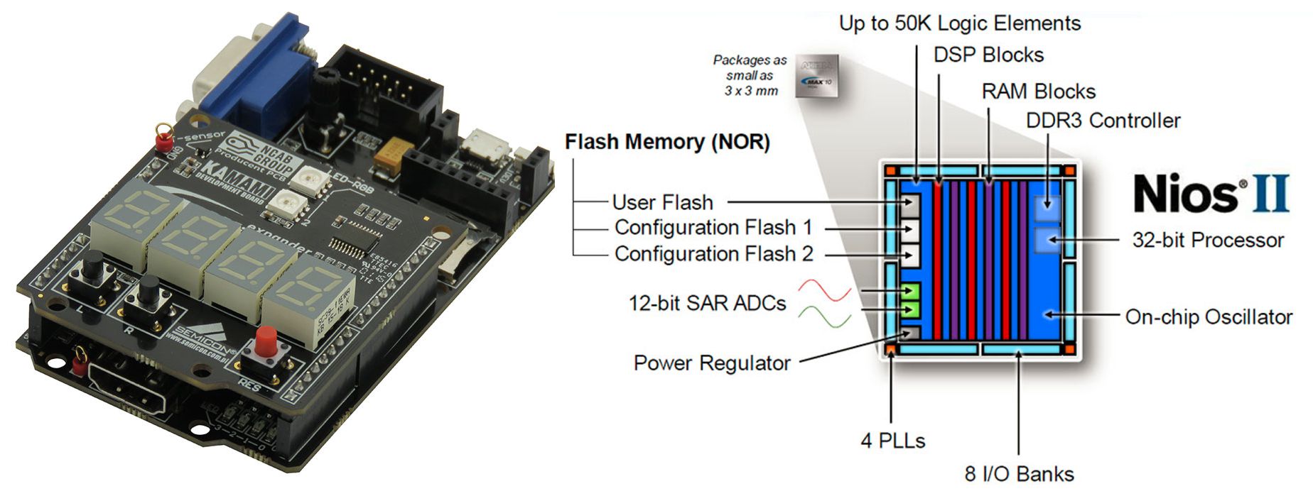 [/su_frame]
Complete implementation of NIOS II 32 bit RISC processor in maXimator board with simple test application written in C language.
Project is fully compatible with free Intel Quartus Prime 17 synthesis tool.
Author: Mariusz Księżak.
[su_custom_gallery source=”media: 522,521,520,519,518,517,516,515″ link=”lightbox” target=”blank” width=”60″ height=”100″][/su_custom_gallery]
[su_button url=”https://maximator-fpga.org/wp-content/uploads/2021/06/NIOS_LED.zip” target=”blank” style=”soft” background=”#ca9a1e” icon=”icon: cloud-download”] Project download[/su_button]
[/su_spoiler]
[su_spoiler title=”Digital voltage meter with 7-seg and VGA displays” icon=”folder-1″]
[su_youtube_advanced url=”https://www.youtube.com/watch?v=xcEONr-CtGI” width=”540″ height=”320″ responsive=”no”]
FPGA implementation of voltage meter (0-2.5VDC range), based on built-in ADC, with 7-segment LED and VGA displays.
Project is fully compatible with free Intel Quartus Prime 17.1 synthesis tool.
Author: Jakub Tyburski.
[su_button url=”https://maximator-fpga.org/wp-content/uploads/2016/02/WoltomierzVGA-z-7seg.zip” target=”blank” style=”soft” background=”#ca9a1e” icon=”icon: cloud-download”] Project download[/su_button]
[/su_spoiler]
[su_spoiler title=”Clock synchronized with DCF signal” icon=”folder-1″]
[su_youtube_advanced url=”https://www.youtube.com/watch?v=Hg4RKKCHUkU” width=”540″ height=”320″ responsive=”no”]
FPGA implementation of clock synchronized with DCF77 signal. Clock automatically changes winter/summer time. Modules are written in VHDL.
Project is fully compatible with free Intel Quartus Prime 17.1 synthesis tool.
Author: Jakub Tyburski.
[su_custom_gallery source=”media: 552,553,554,555,556,557,558″ link=”lightbox” target=”blank” width=”60″ height=”100″][su_custom_gallery source=”media: 392,393,394,395,396,397,398,399,400″ link=”lightbox” target=”blank” width=”60″ height=”100″][/su_custom_gallery]
[su_button url=”https://maximator-fpga.org/wp-content/uploads/2018/03/DCFv4.zip” target=”blank” style=”soft” background=”#ca9a1e” icon=”icon: cloud-download”] Project download[/su_button]
[/su_spoiler]
[/su_accordion]